Boscastle Locomotive Limited
February 2017
Firebox
We (that is Andy Morgan and Mike Playle, plus some help from David Mathews) have made steady progress removing firebox stays over the winter. All the side and back stays are out and most of the throat stays. Andy cuts them using oxy-acetylene and Mike chisels out the shells. Monel stays don’t respond to acetylene so they are attacked with a plasma cutter. We are getting quite good at this now – but I don’t intend volunteering for another firebox anytime soon!
All 276 crown stays are pilot drilled and we will move onto those next.
The aim is to get the boiler ready to travel some time in the Spring in advance of South Devon Railway Engineering calling for it. We have not as yet been invoiced for the second payment which suggests that they are a bit behind their schedule.
Rod Packings
Both the valve and piston rods on Boscastle are sealed by packings made from cast iron. These will have to be renewed as the rods have been taken down in size to restore cylindricity.
Early locomotive rods were sealed with soft packings lubricated with tallow. I have been intrigued as to how a solid packing could affect a steam tight seal as it is not immediately apparent how metal can be made to shrink to deal with the inevitable wear that must arise from two bits of iron rubbing together and also to cope with the side movements that must arise from working clearances and slight misalignments.
How do they work?
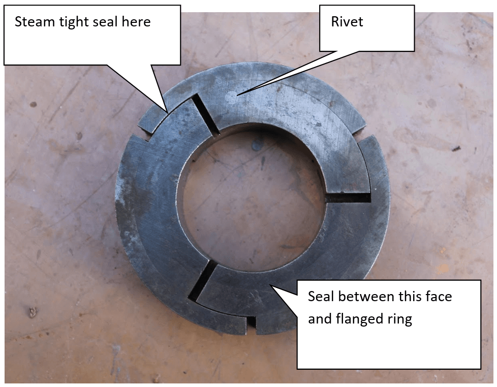
The answer lies in the fact that the seals are segmented and fit together like a 3D jigsaw puzzle. The first photo shows that the segments are cut with 1/8” gaps when the seals and rod start life together.
To achieve a seal requires three conditions to be met.
- Obviously the inner diameter has to match that of the rod
- The inner and outer segments have to seal where they overlap so have to be machined very precisely
- The face (towards us) has to be flat to seal against the flanged ring
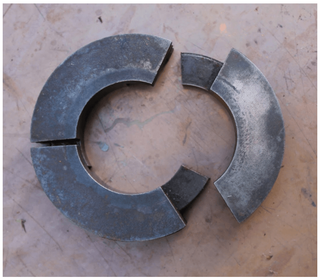
With these conditions met the seal still has to be pressed down onto the rod and up against the flanged ring. The initial contact against the rod comes from two circular springs, shown in the second photo, but the main actuating force to press the segments into position comes from the energising effect of the steam pressure that is being sealed. This forces all the elements together and the higher the pressure the greater the force.
As the seal and rod wear, which they inevitably must, the segments move inwards to maintain contact with the rod. This they can do by reducing the 1/8” gap. The seal between the segments is maintained provided the three segments wear at a similar rate. Sealing will obviously be helped by the fact that the seals are fed lubricant which will help stop small gaps which are inevitable.

How are they positioned on the cylinder block?
The assembly sketch shows how the valve rod seals are arranged. This has been converted from the assembly drawing which had lots of confusing hidden detail lines which I have removed manually for clarity. I have also renamed the parts so that the names better describe the shape of the part or the function.
It can be seen that three sets of seals are arranged in series indicating that the designers acknowledged that some by pass leakage was unavoidable.
The high pressure end is to the left. The seals are assembled by feeding the components into the recess on the valve chamber cover and retaining them with the bush housing. Bolting this in position loads the spring at the high pressure end. Note that this spring presses the flanged rings against the bush housing. It does not preload the seals. The seals have no preload axially as they have .006” longitudinal float.
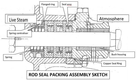
The seals are fed lubricant via drillings (which I have removed from the sketch for clarity). Numbering from the left , seal 1 seals against flanged ring 2. Seal 2 seals against flanged ring 3. Seal 3 seals against the bush housing. Flanged ring 1 acts only as a spacer to transmit spring load.
Because the seal rings work against flat faces they can float to follow transverse rod movements. Note that the guide bush can start with .02” clearance so it does not, in fact, do much guiding and the rod must move up/down and sideways to some extent. The bush housing is sealed against the end cover by a static copper ring seal.
How are these seal rings made?
Seal Ring assemblies start as an outer and inner ring. The inner diameter is sized to precisely match the rod on both parts. The outer diameter of the inner ring is made to precisely enter the recess in the outer ring. The two rings are cut into segments and then riveted together with the step offset shown in the photos. The final operation is to grind the faces flat and achieve a thickness to give the slight end float within the flanged ring. The seals and flanged rings are marked to retain their identity as sets. It is our intention to make these rings ourselves when we are sure that we have identified the correct material.
What is the material?
The drawings call up “special cast iron” and gives a chemical composition which suggests a gray cast iron where carbon exists in graphite form thus enhancing lubrication. Unfortunately it would appear that a British Standard was not available to satisfy the requirement so this gives us the challenge to find something appropriate.

17th January 2017
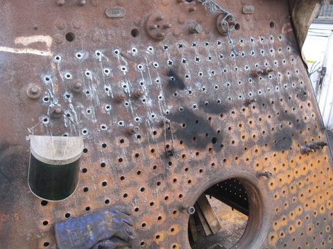
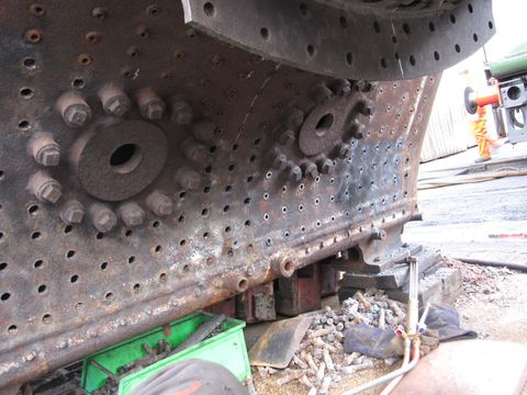
This shows the the last of the stays on the firebox backplate in the process of being burnt out, the stays on the left have been burnt away to release the stay section between the inner and outer plates. The notched stays on the right hand side have had the remains weakened ready to be chiselled out.
3rd February 2017
With the sides and rear now clear of stays, work continues on the throatplate. The stays on the lower left of the photo or right hand throatplate side, have been removed completely, while those furthest away have been burnt out and just require notching and chiselling out.
13th February 2017
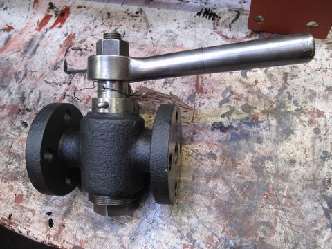
The steam valve that controls the Stones turbo generator has been overhauled and is ready to receive the Klinger packing seals when it is finally fitted to the loco.
13th February 2017
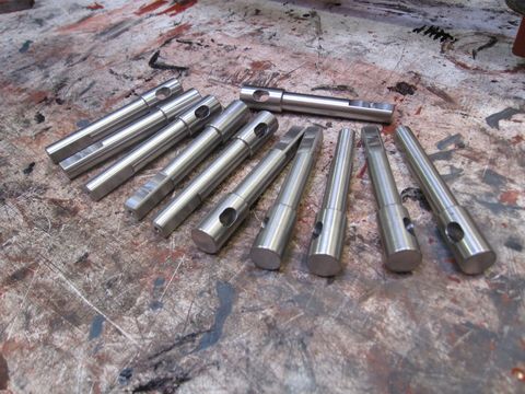
This shows part of a batch of new stainless steel valve spindles for the shut off cocks on the boiler water gauges. Thanks must go to our longest serving volunteer Keith Devereux, who once again persuaded a friend of his to CNC machine these beautifully made items, at no cost to Boscastle.
13th February 2017
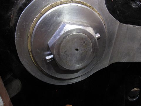
One of the jobs attended to, has been the fitting of securing pins and cotters that ensure that the motion component fastenings cannot come apart. This shows the cotter pin that prevents the small end gudgeon pin nut from coming loose. These pins are not now commercially available, so have to be made 'in house' and carefully fitted to be a snug fit. It was issues with one of these components that was identified as a contributing factor in the near catastrophic failure of 34067 Tangmere at Winchfield in November 2013.

13th February 2017
This shows another type of fixing called a taper pin commonly used to help secure valve gear and coupling rods. This shows a large pin fitted to the right trailing coupling rod cap nut. The pin is driven into the hole through the nut and crank pin until tight so that the nut cannot move. The ends of the taper pin are then spread apart to ensure that it also cannot come out, giving additional protection.
13th February 2017
The AWS battery box that sits prominently on the front of the locomotive has been overhauled and this photo shows the original cast fusebox that attaches to the side of it, restored to as new condition.

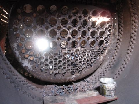
13th February 2017
This shows the firebox tubeplate viewed from inside the boiler. Many of the stays in the firebox combustion chamber (front of the firebox) area are accessible from inside the boiler and are cut out more easily from in there. A pile off cut stay remains can be seen under the bottom of the tubeplate.
Images on this page are copyright A.J.Morgan, M.Playle